26
Feb
How to Install a CNC Touch Probe for Precision Machining
Installing a CNC touch probe is a critical upgrade for any machining center, enabling automated tool and workpiece measurement, reducing setup time, and improving part accuracy. This guide walks you through the process, from selecting the right probe to calibrating it for optimal performance.
1. Select the Right Touch Probe for Your CNC Machine
Before installation, ensure compatibility with your machine’s specifications:
- Probe Type: Choose between 3D touch probes (for multi-axis measurement) or 2D probes (for basic tool setting).
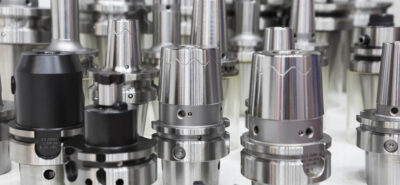
- Shank Size: Match the probe’s shank diameter (e.g., BT30, HSK-A63) to your machine’s spindle interface.
- Trigger Force: Opt for adjustable trigger sensitivity (e.g., 0.1–2N) to handle delicate workpieces or heavy-duty cutting.
- Communication Protocol: Verify compatibility with your CNC controller (e.g., Fanuc, Siemens, Mitsubishi).
2. Gather Tools and Safety Equipment
Prepare the following items:
- Touch probe kit (probe body, stylus, receiver, and cables)
- Mounting hardware (collets, adapters, or tool holders)
- Calibration artifacts (standard balls or ring gauges)
- Basic tools: Wrenches, torque screwdriver, and cleaning supplies
- Safety gear: Gloves, safety glasses, and machine-specific PPE
3. Power Down and Secure the Machine
- Turn off the CNC machine and disconnect it from the power supply.
- Lock the spindle to prevent accidental movement during installation.
- Clean the spindle taper and tool holder interface to remove debris or coolant residue.
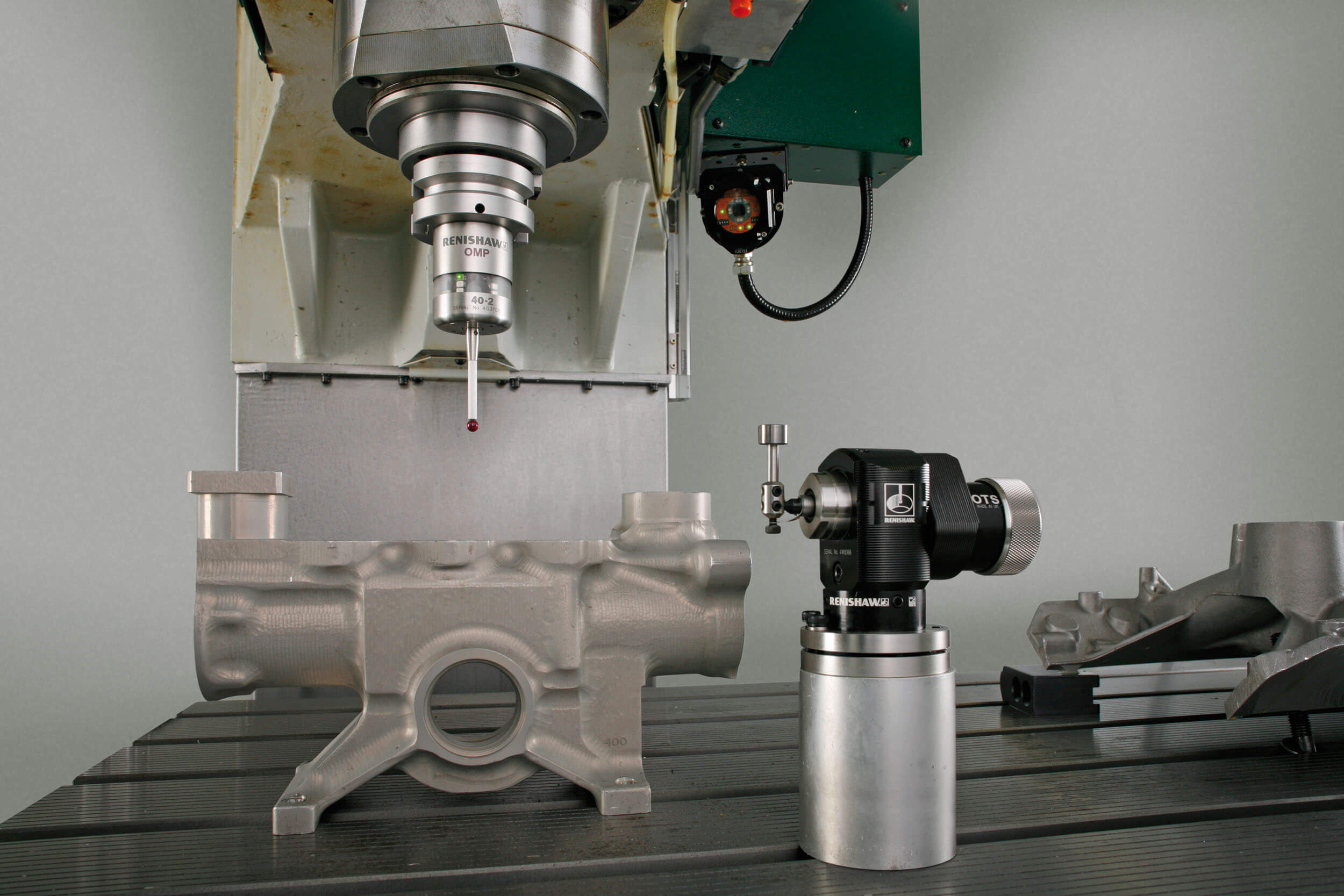
4. Mount the Touch Probe on the Spindle
Option A: Direct Mounting (For Probes with Integrated Shank)
- Align the probe’s shank with the spindle taper.
- Gently insert the probe by hand, ensuring it seats fully into the taper.
- Use a torque wrench to tighten the retention knob to the manufacturer’s specified torque (typically 10–15 Nm).
Option B: Using a Tool Holder (For Modular Probes)
- Attach the probe to a compatible collet or tool holder (e.g., ER collet for flexibility).
- Insert the tool holder into the spindle and tighten securely.
- Verify that the probe’s stylus is centered and does not wobble when rotated.
5. Connect the Probe to the CNC Controller
- Wiring Setup:
- Locate the probe interface port on your CNC controller (often labeled “PROBE IN” or “TOOL SETTER”).
- Connect the probe’s signal cable to the port, ensuring proper polarity (refer to the manual).
- If using a wireless probe, pair it with the receiver following the manufacturer’s instructions.
- Power Supply:
- Some probes require external power (e.g., 24V DC). Connect the power cable to a dedicated outlet or the machine’s power distribution unit.
6. Configure the CNC Controller Software
- Enable Probe Functionality:
- Access your controller’s settings menu (e.g., Fanuc’s “PARAMETER” or Siemens’ “MACHINE DATA”).
- Activate the probe input channel (e.g., set
PARAMETER 3003#5 = 1for Fanuc).
- Set Measurement Parameters:
- Define the probe’s trigger sensitivity, measurement speed (typically 50–500 mm/min), and search distance.
- Configure the probe’s home position (usually the machine’s reference point).
- Test Communication:
- Run a dry test by manually jogging the spindle toward a fixed object (e.g., a vice jaw). The probe should trigger and send a signal to the controller.
7. Calibrate the Touch Probe
Calibration ensures measurement accuracy by accounting for probe offset and stylus geometry:
- Tool Length Calibration:
- Mount a standard tool (e.g., a 10mm end mill) in the spindle.
- Jog the tool to touch a known reference surface (e.g., a machined flat plate).
- Record the Z-axis position and input it into the controller as the tool’s length offset.
- Workpiece Offset Calibration (Optional):
- Use a calibration artifact (e.g., a 50mm ceramic sphere) to set the probe’s X/Y/Z offsets relative to the workpiece coordinate system.
- Stylus Tip Compensation:
- If using a replaceable stylus, measure its effective length and diameter, then input these values into the controller.
8. Perform a Test Run
- Automated Tool Setting:
- Program a simple cycle to measure a tool’s length and diameter (e.g.,
G65 P9810 H__ Z__for Fanuc macros). - Verify that the measured values match the tool’s actual dimensions (±0.005mm tolerance is acceptable).
- Program a simple cycle to measure a tool’s length and diameter (e.g.,
- Workpiece Inspection:
- Use the probe to measure a machined feature (e.g., a bore diameter or pocket depth).
- Compare the results to the CAD model to ensure accuracy.
9. Troubleshoot Common Issues
- False Triggers: Check for loose connections, electromagnetic interference, or coolant contamination on the probe tip.
- Inconsistent Measurements: Recalibrate the probe and verify stylus tightness.
- No Signal: Ensure the probe is powered and the controller’s input channel is correctly configured.
10. Final Checks and Maintenance
- Secure All Connections: Double-check cables and mounting hardware.
- Store Calibration Data: Save probe settings to the controller’s memory or an external device.
- Regular Cleaning: Wipe the probe stylus and body with a lint-free cloth after each use to prevent buildup.
Conclusion
Properly installing and calibrating a CNC touch probe transforms your machining process by automating critical measurements and reducing human error. By following these steps—from mounting to testing—you can achieve sub-micron accuracy and streamline production workflows. For complex setups, consult the probe manufacturer’s documentation or seek training from a certified technician.